Introduction
</span class="fontstyle2">
In cement manufacturing, formation of clinker nodules occurs at the entrance to the hottest part of the kiln with a material temperature of around 1280°C. The clinker is preferably in the form of 10-mm to 25-mm size nodules that exit from the front end of the kiln into the cooler. It is critical that cooling of the clinker is rapid to secure a phase composition that imparts adequate cementitious properties. It is equally important that the heat exchange between clinker and air is efficient to ensure proper cooling, and at the same time maximize the recovery of heat to secondary air, tertiary air, and the related process requirement. The modern cooler must accomplish all of these tasks efficiently and simultaneously.
Like other processing equipment, clinker coolers have undergone significant development over the past years. This chapter describes the advent of clinker coolers with discussion and description of various types of coolers presently available. The chapter also focuses on the reciprocating grate
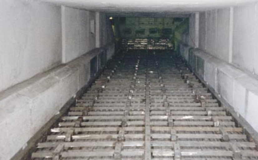
ooler and the latest developments in cooler designs, while tracing the historical development of the reciprocating grate cooler in relation to increasingly fuel-efficient kiln systems. The theoretical mass and heat balance equations that describe the steady state and heat recuperating efficiency are presented, followed by a more practical discussion of how to automate and optimize the operation of the cooler. Figure above shows the interior of most commonly operated grate coolers in cement manufacturing.
At the discharge end of the kiln, the clinker is red hot and contains around 1.0 million Btu per short ton thermal energy. The clinker is also to some extent still reacting chemically toward creation of various clinker minerals. The purpose of the clinker cooling is to recoup some of the heat in the clinker, thereby making it cool enough to handle. We also want to stop the chemical reactions in the clinker at the point most favorable to the cement quality. </span class="fontstyle0">
TYPES OF CLINKER COOLERS</span class="fontstyle0">
</span class="fontstyle0">
What governs the design and selection of a clinker cooler? Surely, today, any design project would include some of the following requirements: low capital cost; optimum cooling rate for good clinker quality; low clinker discharge temperature; least possible impact upon the environment; high heat recovery; low power consumption; low wear and maintenance cost, and reliable to operate, causing minimal downtime; and easy to control so it delivers a steady flow of combustion air at an unvarying temperature to the kiln and calciner. These criteria are of immediate interest to a manufacturer of cement who buys a cooler for clinker. The designer of the clinker cooler looks at these criteria and tries to optimize the design, depending upon the weight of each of these individual criteria.
Over the years, the criteria that are used to select coolers have changed. The technology of clinker cooling has developed as well, so that many different types of clinker coolers have been applied since the infancy of the portland cement manufacturing industry in the late l9th century. The following sections will describe the most common clinker coolers with particular emphasis on the reciprocating grate cooler.
</span class="fontstyle0">
Planetary Coolers</span class="fontstyle0">
</span class="fontstyle0">
The name of the planetary cooler is derived from the fact that it circles the kiln like planets circle the sun. A planetary cooler consists of a number
| of cooling tubes mounted around the circumference of the kiln shell |
(Figure 3.8.2). The advantage of the planetary cooler is its simplicity: it requires no excess air to handle, no fans or motors, and no instruments. It is self-adjusting. The power consumption is only about 0.5 to 1 kilowatt-hours per ton of clinker added to the kiln drive and exhaust fan, making it the lowest for any kind of clinker cooler. The heat losses through radiation and sensible heat in clinker are between 0.40 and 0.45 mega-joules per kilogram of clinker for an economical dryprocess kiln even and lower for wet-process kilns. Planetary coolers have been used successfully for kilns as big as 4000 metric tons per day, though not in North America.
These coolers were popular in the 1960s and 1970s when many dry process 4-stage preheater kiln systems were built around the world. In North America, most of the dry process kilns were supplied with grate coolers.
The planetary cooler does not allow withdrawal of tertiary air for a calciner. As most kiln systems built today have calciners, the planetary cooler is becoming a relic of the past. One weakness of the planetary coolers is that they can be costly to maintain. The cooler inlets often wear out too fast due to the thermal, mechanical, and abrasive stress to which they are subjected. To decrease the resulting maintenance and downtime, over the years there has been continuing improvement by trials with inlets made of high temperature metal alloys or ceramic materials.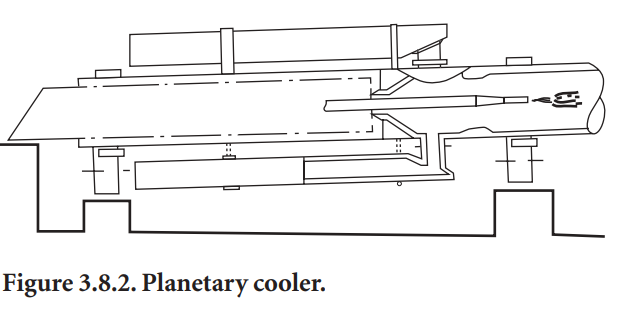
Rotary Coolers
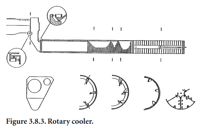
Some of the earlier coolers were almost like another kiln following the clinker burning tube or, using another picture, take the planetary coolers, combine them into one tube with its own support and drive, and you have a rotary cooler (Figure 3.8.3).The modern rotary cooler is equipped with ceramic lining and lifters based upon the development of the planetary cooler. Special seals at the kiln outlet and the cooler inlet are required. To avoidspillage from the inlet, the cooler is inclined 2.5° and given a speed of rotation of 3 rpm. The power consumption for the drive is about 3.5 kWh/ton. The clinker temperature is 200°C to 250°C, but is reduced to about 150°C by water injection in the outlet. Presently, no cooler of this type is used in North America.
Shaft Coolers</span class="fontstyle0">
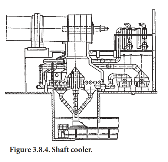
It should be added that shaft coolers of somewhat different design, such as the Niems cooler, have been used very successfully for modern lime burning kilns. Burnt lime has a rather uniform grain size distribution and therefore is much easier to cool in a shaft cooler than cement clinker.
Traveling Grate Coolers</span class="fontstyle0">
Grate Coolers
The cooler consists of one or several grate sections. The sections are defined by their location or their function, or by whether they are connected to a certain drive (for instance, ‘inlet grate,’ ‘2nd movable grate,’ etc.). Each grate consists of a certain number of rows of plates. The plates have been the subject of much development in the 1990s, as will be described later. The air to the grates is supplied in various ways: through air blown into compartments under the grates or blown into ducts (often called ‘airbeams’) connected directly to a limited number of grates
A typical cooler built between 1970 and 1990 works in the following fashion. From the kiln, the clinker drops onto a stationary air-quenching grate. This grate may be horizontal or inclined. It consists of one or several rows of plates. In the cooler shown in Figure 3.8.5, there are three movable grates; the first is with an inclination of a few degrees, and the other two are horizontal. Below the grate, the cooler is divided into a number of compartments, each provided with fans equipped with adjustable guide vanes for automatic air flow control and minimum power consumption. Clinker spillage through the grate is collected in hoppers and removed through airtight flap valves to the clinker conveyor. Since the 1990s, the underside of the plates in the quench grate and the first grate have been connected directly to cooling fans. This has allowed better individual adjustment of air to different parts of the grate.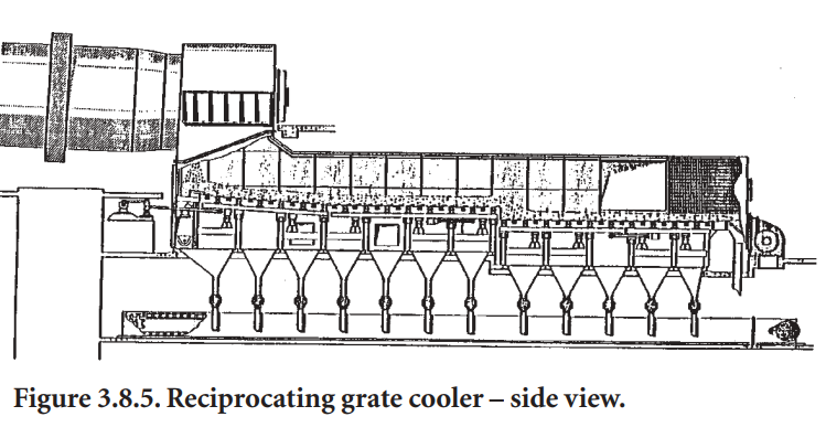
The efficient sealing between the compartments permits operation at high and different pressures in the various compartments. With a normal clinker bed thickness of 600 mm, the pressure drop at a constant air flow per unit area will decrease from about 5.9 kPa in the hot end to about 2.0 kPa in the cold end. The fans are sized accordingly so that the maximum pressure decreases from 7.3 kPa to 2.9 kPa. For trouble-free operation, it is an advantage to use more air per grate or unit area in the hot end, up to 200 kg/min/m2, and less in the cold part, say 40 kg/min/m2.
The width of the grate is reduced in the inlet in order to spread the clinker more evenly. Together with the high air flow and the thick layer of clinker, this helps to provide a uniform clinker bed thickness, which in turn gives a uniform air flow over the width of the grate. This is essential not only to avoid local overheating of the grate, but also to avoid “snowmen” – the clinker is kept moving throughout the whole grate until the individual particles have lost their stickiness and ability to cling together.
The clinker is pushed through the cooler by the reciprocating movement of rows of plates. Usually, every second row of plates in a grate is movable. The other rows are stationary.
A crank arm moves the movable frame on older coolers. The rows of plates are moved by a connecting rod which is centrally fixed to the movable frame, so that twisting is avoided. The rod goes through the wall via an airtight seal and is driven by a direct current motor or by a hydraulic piston. In the 1980s one supplier started to offer a pendulum suspended frame, such as shown in
Figure 3.8.6. This method of moving the frame is claimed to be particularly effective at keeping tight tolerances of movement to minimize wear on side castings. The activation by a single hydraulic cylinder with an asymmetric stroke (slow forward, fast back), helps minimize mixing of the clinker and, thereby, bed resistance to airflow. The speed of frames, whatever way they are moved, can be varied between 3 and 30 strokes/min. In normal operation, 5 strokes/min is adequate, providing ample spare capacity.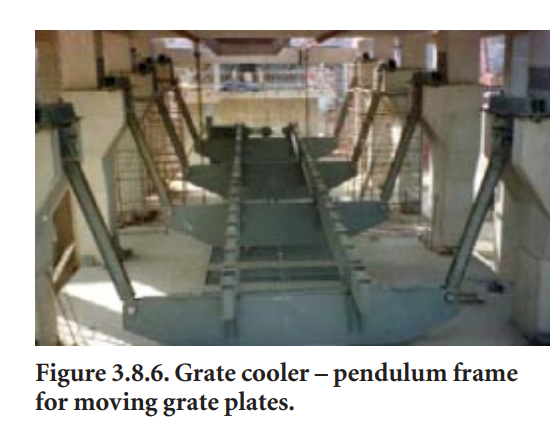
Before the 1990s, all grate plates, both the movable and stationary, were of identical design. They were cast with circular holes – in the front part of the cooler they were made of heat-resistant steel; in the cold part, of cast steel. The shoes of the plates were bolted to a cross beam away from the heat. All designs allow removal from underneath where there is easy access to the grate through the undergrate compartments.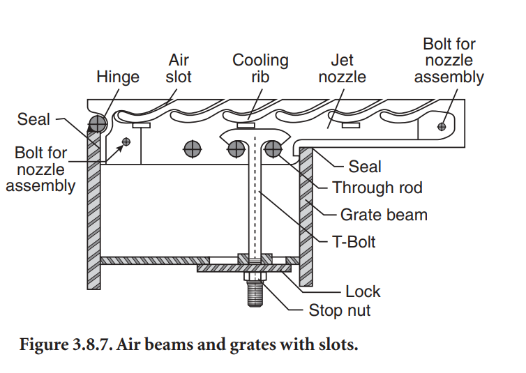
In the late 1980s a new type of grate plate connected to an airbeam was introduced. This plate contains inclined and curved slots rather than holes (Figure 3.8.7). The slots are shaped by small blades that are easily replaced from the top of the plate. This innovation was so effective that by the 1990s all major suppliers were offering grate plates with slots instead of holes for
the hot part of the cooler. The suppliers’ plate designs varied, but they all contained a pocket where cooled clinker could rest and minimize metal wear, and they were all connected directly via an airbeam to a fan rather than being supplied with air through an undergrate compartment. These changes resulted in better protection of the grate from thermal and abrasive stress caused by hot moving/sliding clinker and improved cooling of the clinker by better control of air flows.
The clinker discharges from the cooler across a grizzly to a hammer mill or hydraulic roll crusher located in the cooler outlet. The crusher may be installed in the middle of the cooler, before the last grate, to break up lumps and large clinker, and to ensure their efficient cooling. The thermal stress on the crusher is obviously greater in the middle than at the end of the cooler.
When a cooler is operating with a thick clinker bed and evenly distributed clinker and air, and is designed with sufficient retention time of clinker in the cold end, hot lumps do not cause severe problems.
Grate Coolers Without Excess Air Vent Stack</span class="fontstyle0">
</span class="fontstyle0">
The excess air from the grate cooler normally has to be dedusted and exhausted through a stack. This is costly and may be difficult to get permission for from licensing authorities. To avoid these problems, some plants have installed a combination of a short grate cooler and a gravity or
“G-cooler” or they have installed recirculation of the excess air.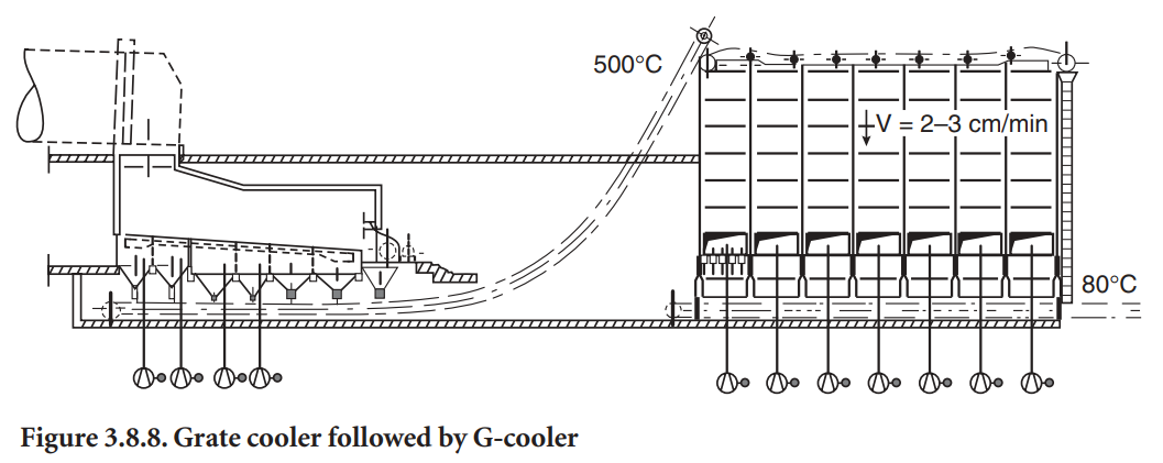
The gravity cooler (Figure 3.8.8) is used in connection with a short grate cooler, furnished with just the amount of air needed for combustion in the kiln and calciner. The clinker discharged from the grate at a temperature of about 500°C is crushed and carried to the top of the gravity cooler, through which it drops slowly at 2 - 3 cm/min, while cooled indirectly by ambient air blown through cooling tubes. After about two hours of slow downward travel, the clinker is discharged at a temperature of about 100°C. The power consumption for the fans of the G-cooler is around 1 to 2 kWh/ton. Control of hood pressure and the conveying of occasionally very hot clinker between grate and gravity cooler requires special attention to make this system operate well.
Another way to avoid dedusting the excess air from a grate cooler is to cool the air in a heat exchanger and then recirculate it to the grate (Figure 3.8.9). The heat exchanger is designed so that ambient air is blown on the outside of the cooling tubes through which the excess air from the cooler is drawn.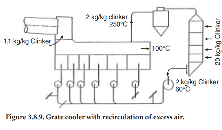
Cross-Bar™ Cooler
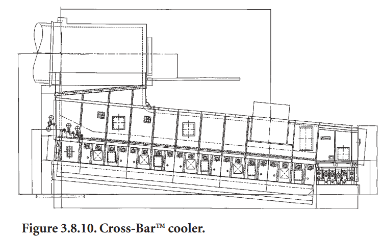
of grate plates moving back and forth, but by wedge-shaped bars suspended above the grates, which are all stationary (Figure 3.8.10). These bars move back and forth and have inspired the name “Cross-Bar™ Cooler.”
Since the plates no longer move, they have been made larger. The traditional size of a cooler grate is 30x30 cm; the cross bar cooler plates are 1x1 m. Furthermore, each plate is supplied with an amount of air that is individually and dynamically adjusted to fit the cooling needs of the moment. This is accomplished by a mechanical flow regulator valve located in the air supply channel affixed underneath the grate plate. This regulator passes air from the undergrate chamber to the holes in the plate as shown in Figure 3.8.11. This eliminates the need for airbeams between cooler fans and
grate plates, and the mechanical problems associated with them. Currently, there are only a few crossbar coolers in cement operation. The vendor claims the cooler is considerably more efficient at heat recuperation than ordinary reciprocating grate coolers. The amount of cooling air is reduced from 2.8 to 1.9 kg air per kilogram clinker, resulting in a low power consumption of 4.0 kWh/ton of clinker cooled.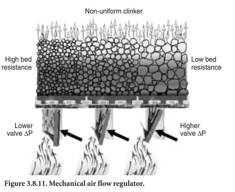
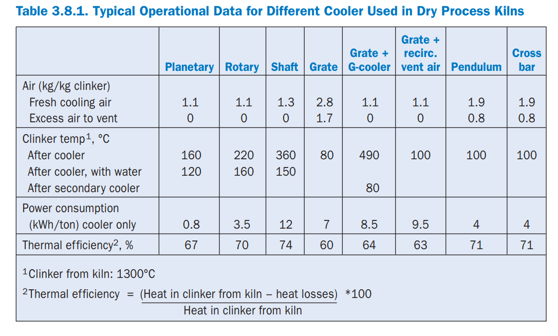
COMPARISON OF DIFFERENT COOLER TYPES</span class="fontstyle0">