Mass and Heat Balances
In the previous chapters we have mentioned the varying amounts of secondary air and temperatures found in different types of clinker cooler systems. To better understand these differences, we might ask how much of the heat contained in the clinker dropping into the cooler has been recuperated to the air returned from the cooler to the kiln system?
Some of the heat entering the cooler will be lost in the cooled clinker, radiation, and possibly the vent air. The amount recuperated is a measure of the thermal efficiency of the cooler. The more recuperated, the more thermally-efficient it is.
To calculate the thermal efficiency, it is necessary to establish mass flows, temperatures, and heat flows. Figure 3.8.12 shows a typical clinker cooler with its heat inputs and outputs. The thermal efficiency of the cooler is defined as the relationship between the heat recuperated and total heat input as shown in the equation in the figure. The lower the heat losses in clinker, vent air, radiation, and convection, the higher the amount of heat recuperated in secondary air and the higher the thermal efficiency. 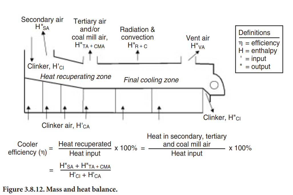
Heat flow is a function of mass and temperature. The higher the mass and temperature of secondary air, the more heat is recuperated. The air used for combustion in the kiln and calciner, plus the air excess creating the oxygen we measure in the kiln system, comes from the primary air supplied through the burner(s), and the secondary and possibly tertiary air drawn from the cooler. For a given combustion air need, to get the amount of secondary air and thus the cooler thermal efficiency to increase, the quantity of primary air and/or infiltration air must be decreased. It is important to maximize the amount of secondary air by minimizing primary and air infiltration rates and to maximize the secondary air temperature by minimizing cooler heat losses.
Since the amount of combustion air depends on the overall fuel consumption, it becomes clear that the type of kiln system influences the thermal cooler efficiency considerably.
A modern-type preheater kiln, consuming 3.0 million Btu per short ton clinker, should be operated at a thermal efficiency between 64% and 68%, if well adjusted. A long dry kiln, consuming 4.0 million Btu per short ton, should run between 68% and 72%; and a wet-type kiln, consuming 5.0 million Btu per short ton, between 70% and 75%. Nevertheless, many clinker coolers are operated at considerably lower thermal efficiencies. It is evident that operating a clinker cooler at peak thermal efficiency improves overall heat consumption considerably.
For any given grate cooler, one can usually measure the amount of cooling air blown into it, as well as the amount of vent air and coal mill air exhausted. The amount of secondary air is calculated by difference or, perhaps, from the amount of coal, backend oxygen, and primary air used. Typical mass balances are shown in Table 3.8.2 
Once the temperatures of the various material streams, their specific heat capacity, and the radiation losses have been determined, one can calculate a heat balance, such as the one shown in Table 3.8.3.
When the balance is established, the cooler heat recuperation efficiency can be calculated as follows:
((Heat entering cooler) – (Heat lost in excess air, clinker, and radiation)) /
(Heat entering cooler) x 100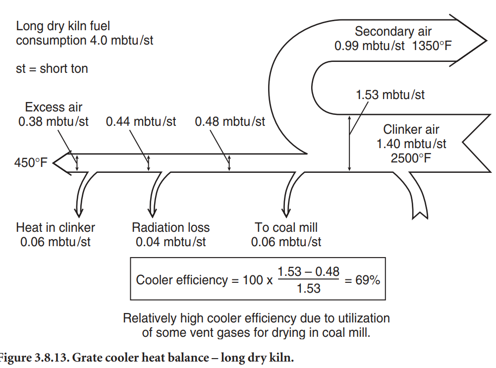
An example is given in Figure 3.8.13. As mentioned earlier, a modern clinker cooler should have an efficiency of 64% or better no matter what kiln it serves. This means that it should be able to move about two-thirds of the heat from the clinker exiting the kiln to the combustion air entering the kiln system.
Automatic Control of Grate Coolers
Three groups of machine adjustments are usually automated to obtain: 1) constant air flow through the clinker bed in terms of mass of air per unit area and per mass of clinker, and
2) constant, slightly negative pressure (suction) in the kiln hood. An example is shown schematically in Figure 3.8.14.
The primary objective of a clinker cooler control system is to stabilize the cooler operation and thereby provide a more uniform flow of heated air for combustion in the kiln and possibly the calciner. The secondary objective is to provide a controlled response during kiln upsets so that the upsets have a minimum impact on the primary objective.
Single and cascade analog controllers, or digital equivalents of these controllers, are the most common ones in use. Ideally, the grate cooler is controlled by one algorithm which optimizes the cooler operation during normal operation while a second control algorithm steps in during upset kiln conditions to ensure that the cooler is not damaged by high temperatures or mechanical problems.
The pressure in the undergrate compartments and air beams (if present), the flow of air into or out of fans, and the speed of the movable grate frame are all controlled by PID loops. Other parameters are monitored simply to ensure they are within a desired operating range. These include fan motor current, kiln speed, motor running status, excess air, and grate plate temperatures.
Using undergrate pressure to control grate speed is acceptable if cooler conditions remain near ideal. To avoid problems associated with erratic first and second compartment pressure, both first and second compartment pressures can be measured for determining a weighted average undergrate pressure. This smoothes out the undergrate pressure and often lets the cooler run steadier.
The finer the clinker, the harder it is to blow air through the bed. With the control loop in automatic mode, a decrease in clinker size will result in an increase in undergrate pressure, until the control loop has sped up the grate, causing a lowering of the clinker bed depth. Conversely, very large clinker will result in unusually low undergrate pressure which will decrease cooler speed and result in excess bed depth, and may even overload the drive. The cooler control system should include elements that detect and correct these conditions.
In the case of a two- or three-drive cooler, the second drive should be controlled by the undergrate pressure of its first compartment. When the second drive’s first compartment is too large for its pressure to be successfully used in connection with speed control, the second drive has to follow the first drive. In that case, the first drive’s speed multiplied by a factor represents the second drive speed. The second drive’s speed should always be higher than the first drive’s speed to avoid clinker piling up between the two drives.
Occasional high grate plate temperatures in the first and second compartments can represent an obstacle to optimizing cooler compartment airflow distribution. During upset conditions where high grate plate temperatures occur, one may have to increase the cooler movable grate frame speed for safety reasons. The grate plate temperature is then permitted to manipulate the undergrate pressure setpoint. As grate plate temperature increases, it will decrease the undergrate pressure setpoint which speeds up the cooler movable grate frame drive.
In one particular case, this safety interlocking resulted in no grate plate failures for two years where, in the past, grate plate failures had been an ongoing problem.
In some cooler systems, high vent air temperatures will result in automatic opening of a tempering damper in the vent airduct to protect downstream equipment from overheating. The vent air volume increase caused by the opening of this damper or even just by the high vent temperature may make the total volume exceed the capacity of the vent fan. If this is a constraint, it may be prudent to automatically reduce undergrate compartment airflows in the latter part of the cooler to restore kiln hood draft control when the vent air temperature (measured before the introduction of tempering air) exceeds a certain threshold valve.
In applications where vent fan capacity and high clinker discharge temperatures are a problem, the kiln hood’s draft can be controlled as well by the last compartment fan. By doing this, it is possible to increase the amount of cooling air and to lower the clinker discharge temperature during normal operation. In this mode of control, the vent fan is run on fixed speed close to maximum capacity. During upset conditions, the amount of cooling air is reduced, resulting in a higher clinker temperature, which would have happened anyway. In a few coolers with limited venting capacities, this control approach has led to considerably lower overall clinker discharge temperatures.
Finally, in order to minimize the need for control room operator involvement, other attractive control features to strive for include automatic initialization of dampers to the full closed position on fan startup, automatic reduction in airflow on fan achievement of maximum motor current, and automatic airflow increases programmed for kiln startup.
Optimization of Grate Cooler Operaiton
A smooth cooler operation depends upon many factors. In the preceding paragraphs several of the important design features that affect the operation, such as burner pipe location, cooler width, and control loops, have been mentioned. In the following section, these points have been revisited, while also dwelling on the fact that optimization of a clinker cooler can be divided into three tasks: 1) maximizing the amount of secondary air, 2) maximizing the secondary air temperature, and 3) maximizing the uniformity of the operation.,
Burner Pipe Position</span class="fontstyle0">
The first step in optimizing a cooler operation begins in the kiln. The burner position has a crucial influence upon the kiln and cooler performance. Long wet and dry kilns with a fuel consumption of more than 4.0 million Btu per short ton of clinker, which were common in the past, needed high amounts of combustion air. Low secondary air temperatures ensured a fast clinker cooling inside the kiln, and the overall thermal efficiency of the cooler was acceptable. Today’s lowfuel-consuming kiln systems have low combustion air requirements, thus giving high secondary air temperatures and slower clinker cooling.
Figures 3.8.15 and 3.8.16 show the difference between two burner pipe positions. Positioning the burner tip at the kiln nose or even into the kiln hood (Figure 3.8.15) means that the flame ignition takes place close to the kiln’s discharge, thus keeping 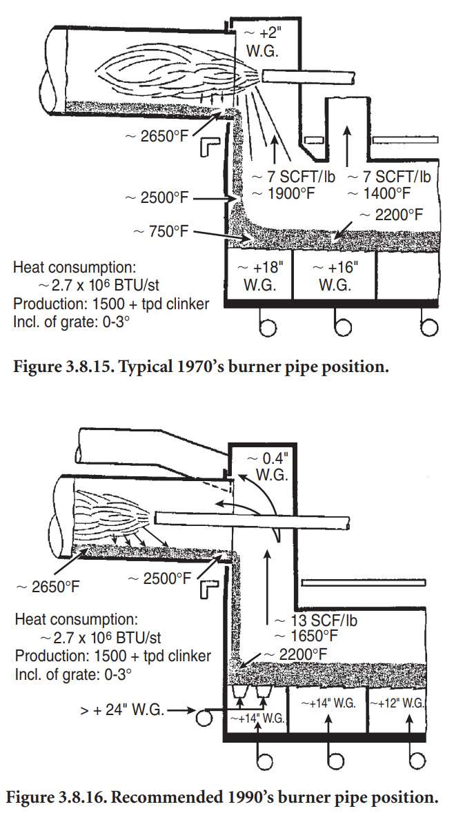
the clinker hot until they drop into the cooler. This can have several undesirable consequences as follows:
• The clinker discharged onto the clinker bed can form large clinker agglomerations, leading to
poor cooling rates because only the clinker closest to the grates are rapidly cooled.
• High temperature clinker reaches the discharge end of the cooler, resulting in elevated clinker
discharge and vent air temperatures. The overall cooler thermal efficiency decreases and fuel
consumption increases.
• High secondary air and kiln clinker discharge temperatures can result in a severe “snowman”
formation, especially if coals with high ash content are used. In addition to all these disadvantages, operational and maintenance problems are likely to occur.
In contrast, positioning the burner tip approximately 1 to 2 m into the kiln (Figure 3.8.16) improves the kiln’s own heat recuperating and cooling zone.
The pre-cooled clinker drops at a lower temperature into the cooler and the secondary air temperature drops. The requirement to cool the clinker quickly is fulfilled. The clinker reaches the latter clinker cooler zones at a lower temperature, which results in lower clinker discharge and vent temperatures. Less required cooling air relieves the vent air system and saves considerable electrical energy. The overall cooler thermal efficiency improves. In addition, the cooler now runs at a higher availability and lower maintenance cost. The formation of “snowmen” is unlikely.
There may be one drawback in pushing the burner into the kiln – it might represent a problem in regard to burner refractory life. Good results were experienced with extreme high strength lowcement type refractories on burner pipes in very severe applications.
Maximizing the Amount of Secondary Air
Low primary air and low air infiltration rates at the kiln discharge maximize the amount of secondary air. Low primary air rates can only be accomplished with semi-direct and indirect firing systems that offer primary air rates as low as 6%. Low air infiltration rates at the kiln discharge can be accomplished with good hood sealing and an effective kiln discharge seal.
Many plants now employ an effective leaf-type kiln discharge seal where overlapping sheets of high quality steel ride on the kiln cowling. This arrangement exhibits little tendency for clinker to pry open the seal. A puffing kiln hood does not open a gap between leaves and the air cowl. This seal has proven itself in many applications. Repairs are easy and overall costs are low.
If the kiln system has a calciner, it is important that as much of the air as possible used for combustion comes from the clinker cooler. Thus any potential opening to ambient air between the calciner and the cooler should be kept as tight as possible. Such openings could be inspection doors, material discharge flaps and damper housings on tertiary air ducts, and kiln material inlet seal and kiln riser poke holes if an in-line calciner is used.
Maximizing Secondary Air Temperature
Maximizing the secondary air temperature means getting the best heat transfer between clinker and cooling air. The heat transfer is optimized by 1) optimization of clinker bed distribution, and 2) optimization of the cooling air distribution.A clinker cooler basically is a heat exchanger. In contrast to most heat exchangers, both mediums – clinker and air, come in direct contact with each other. Therefore, the effectiveness of heat exchange largely depends upon the surface with which both mediums come into contact. In a clinker cooler, the more uniform the clinker size distribution and the clinker granulometry, the more effective the heat transfer.While the clinker size, for the most part, cannot be altered, the overall heat transfer can be optimized with a good, uniform clinker bed distribution.The fact that especially large diameter type kilns tend to discharge fine clinker on the kiln’s load side and coarse clinker on the opposite side can make it difficult to get good clinker distribution. Due to the high air resistance of a fine clinker bed, “red rivers” often are inevitable. Studies show that “red rivers” can cause a variation in air distribution of 1:6 between the fine and coarse clinker side and can even cause clogging of the bed. This is why grate plates sometimes become red hot in places. “Red rivers” also cause an increase in clinker discharge temperature.Measures for improving the clinker distribution should start at the cooler inlet. Where “snowmen” cause poor clinker distribution, the cooler back and sidewalls can be kept clean with the help of compressed air cannons. Some improvements are possible by slowing down the movement of the fine clinker bed and diverting more fine clinker to the coarse cooler side, thus increasing the overall clinker bed resistance which pushes more air through the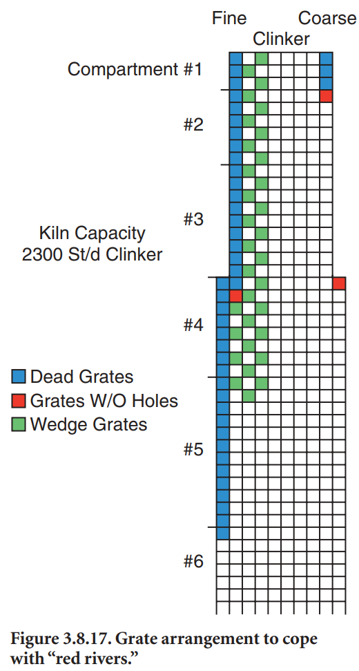
fine clinker bed. This diversion can be done by using wedge-type grates with 125-mm or 200-mm high faces. The grates are arranged in a checkerboard pattern as shown in Figure 3.8.17.
An often successful way to improve the situation is to narrow the cooler grate area on the fine clinker side. By doing so, the clinker bed becomes narrower and often eliminates a severe segregation of fine and coarse clinker. It is recommended that the cooler inlet grate width not exceed 2.5 m for kiln capacities up to 2,500 metric tons per day of clinker.
Figure 3.8.17 shows that some air holes in corner grates are blanked off. Corner areas often have a low clinker load which results in heavy air channeling and bypassing the clinker load. Blanked off air holes ensure that cooling air is diverted into the clinker load.
When severe “red river” conditions exist and loss of cooler grates are experienced, “Ondufin” grates can be applied. The grates have cooling fins on the underside which increase the cooling surface. The grates stay cooler and last longer. In addition, if a grate is burned through, the fins prevent large clinker spillages for a considerable time.
When “red river” conditions in a pre-1990’s style cooler are extremely severe, compartments can be divided into two sections. Two cooling fans, one on each cooler side, assure that both grate areas, the fine and the coarse side, receive the proper amount of air. Or, the design can be upgraded to one with airbeams or mechanical air flow regulators for small groups of grates.
Some suppliers, borrowing from the airbeam technology, offer a grate plate design for pre-1990’s coolers where the air has to travel through a labyrinth in the grate – first up, then down – before exiting into the clinker bed. This provides an effective clinker seal that reduces the amount of clinker falling through the grate plates to the undergrate compartment.
Increasing the clinker bed thickness generally improves the overall clinker distribution and heat transfer. Good results have been experienced with clinker beds up to 1 meter deep. In addition, lower grate speed has had a positive effect upon grate wear rates.
High undergrate pressures and airflows adversely affect the conveying action of a reciprocating grate. High air pressures can reduce the friction between the clinker and the grate, which in turn can speed up the movement of the clinker toward the cooler discharge. The air, which expands as it rises in the bed, causes the clinker at the surface to be fluidized. The result might be that clinker flows down the slope if the grate area is inclined or that the clinker can only be moved with extremely high reciprocating speed on horizontal type coolers. To prevent clinker from flowing forward, the single grate surface should be at least horizontal.
Experience has shown that the best results can be attained with a maximum of 4.7 to 5.5 kPa undergrate pressures in horizontal and 3 degree inclined coolers, and 2.0 to 2.5 kPa in old 10 degree inclined coolers.
AIR DISTRIBUTION VERSUS OVERALL COOLER EFFICIENCY</span class="fontstyle0">
Optimized air distribution also improves the overall thermal cooler efficiency and prevents damage to grates due to overheating. To achieve this goal, predefined amounts of cooling air need to be established for every cooler compartment. Coolers with airbeams or mechanical air flow regulators can refine the air distribution even more to sections of grate plates or to individual plates.
The optimization of airflow is especially important for the heat recuperating zone. Too high amounts of air do not give maximum secondary air temperature. Too low amounts of air elevate the clinker discharge temperature. Too high amounts of air also promote fluidization of the clinker. As the finer clinker particles are likely to be entrained in the locally intensified air flow, high amounts of dust cycles between kiln and cooler are likely. Dust particles might also be picked up from highly fluidized areas and concentrate in others, thereby intensifying any “red rivers.”
Extremely high airflows also promote heavy air channeling, giving a poor heat exchange for a grate cooler of 1970’s to mid-1990’s vintage. It is recommended that maximum airflow not exceed approximately 140 normal cubic meters per minute per square meter of cooler grate area. Figure 3.8.18 shows a chart of optimized cooling air distribution for a typical eight-compartment reciprocating grate cooler. The first five compartments (including quench compartment) supply secondary air and tertiary air if applicable; compartments #5 through #8 cool the clinker to a final temperature of approximately 100°C. Lowering the clinker discharge temperature further with more air increases the electrical power consumption considerably. Depending upon the total amount of cooling air used, the power consumption for the cooling fans can run between 3 and 8 kWh/ton of clinker, plus up to 4 kilowatt-hours for venting. 
As can be seen, the maximum specific amount of air per unit of grate area goes into the quench compartment and compartment #1 to quench the clinker and assure low grate temperatures. The specific airflows per unit of cooler area gradually decrease toward the cold end of the cooler.
Some older coolers still have one cooling fan for up to three compartments. The distribution of air into each compartment is difficult since the cooling air will try to migrate into the compartment with the lowest undergrate pressure. This is especially true when heavy loads travel down the cooler. Employing one air fan for each compartment and making sure they are well air-sealed from each other will result in a lower overall clinker discharge temperature and less air usage.
In order to allow deep clinker beds and defined airflows in each compartment, one needs good undergrate compartment sealing, especially where drag chains pass through compartments. Where drag chains are located below the cooler, the best sealing is accomplished with flap valves controlled by level indicators located in the undergrate compartment. The flap valves are only operated if material inside the compartment reaches a certain level. Figure 3.8.19 shows this arrangement.
Efforts to avoid the mixture of low and high temperature cooler air above the clinker bed are important as well. If considerable amounts of air from the back-end compartments mix with air from the heat recuperating zone, the secondary air temperature drops while the vent air temperature increases. We can take some steps to avoid secondary (and tertiary) air from mixing with the vent air. At the point in the cooler where these two air streams split off in different directions, an arched brick wall or some hanging stainless steel dampers can be installed. From this part of the cooler, the cooler roof should be sloped at approximately 15° as it approaches the cooler 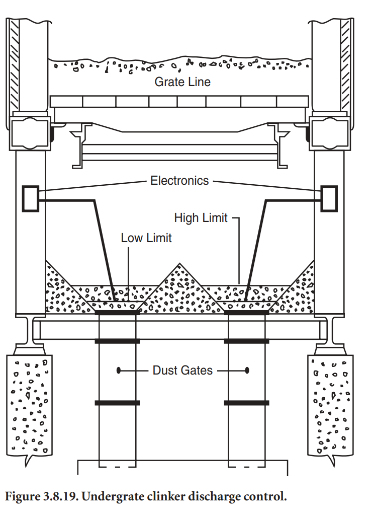
throat and 5° to 10° as it approaches the vent air take off. The sloped roof changes the bullnose from 90° to approximately 75°. The resulting lower velocity in the lower part of the cooler throat reduces the amount of fine particles returned to the kiln.
Wherever possible, the cooler throat velocity should be held below 7 m/sec. New systems should even be designed with velocities as low as 3.5 m/sec.
A proper and uniform distribution of the clinker upon the grate is of importance, as already mentioned. Ideally, you would like a giant stirrer to mix the large and small clinker (that are segregated as they fall into the cooler) together again, and then have them spread out in an even layer upon the grate. Equipment that has been used for this purpose includes: 1) sloped inlet, 2) watercooled adjustable steel impact inlet plate, 3) reducing effective grate width (horseshoe pattern of inlet grate plates), 4) stationary quench grates at the front of the cooler, and 5) spreader beam across the cooler. In the 1990s another interesting method was introduced. It consists of aeration of a sloping bed at the inlet end of the grate. This area is provided with a series of fixed windboxes arranged stepwise and equipped with cast metal grate elements designed so that no particles can fall through them (Figure 3.8.20), that is, with the airbeam and pocket grate technology mentioned earlier.
A considerable pile is built up over the grate plates, which contain pulsating air. The air expands the pile and in particular moves and mixes the finer clinker with the coarser. At the same time making the upper portion of the pile slide gently into the cooler while it is being spread out. 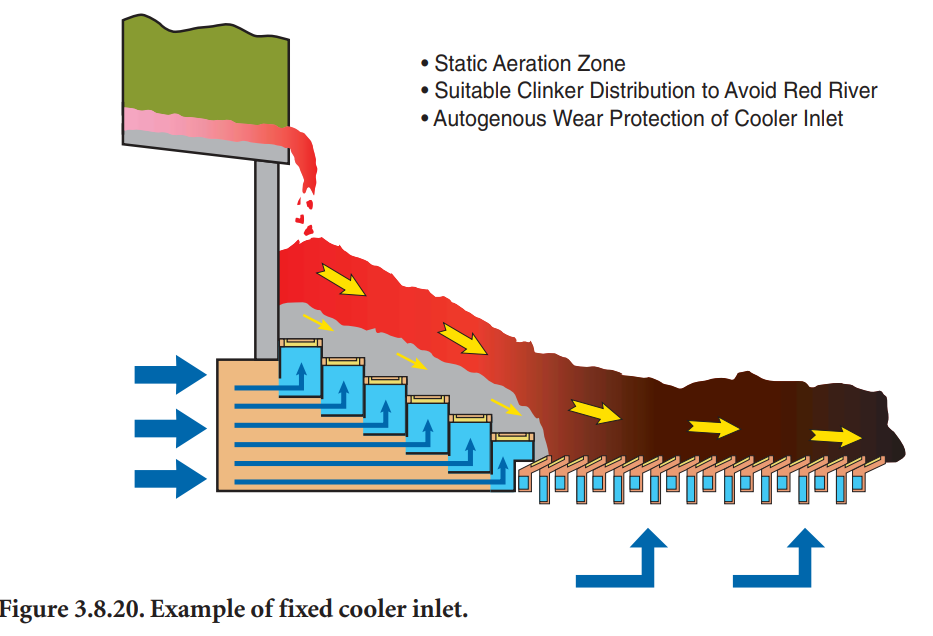
</span class="fontstyle0">
</span class="fontstyle0"></br style=">