Introduction
Fans are tested in laboratories with test setups that simulate installations that are typical for that type of fan. Usually they are tested and rated as one of four standard installation types as designated in AMCA Standard 210. These standard installation types are shown in Figure 1.
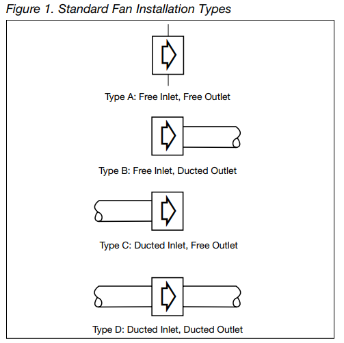
Products that are rated and certified by AMCA must illustrate that they have been rated by one of the installation types shown above. In addition to listing the test type, the ratings must also be published at a standard air inlet density. The fan industry has adopted a standard density of 0.075 lb/ ft3 at 70°F at sea level and at a barometric pressure of 29.92" Hg. All manufacturers’ ratings are made at, or adjusted to, this standard. Whenever a fan is operated in a system where any or all of these conditions vary, corrections must be made in order to obtain accurate results. It’s not enough to make fan performance adjustments based on density corrections. The designer must also consider what effect the variables that are influencing the fan air density might have on the structural components of the fan. Temperatures other than 70°F can cause an alloy to become too pliable or brittle. Speed adjustments can exceed the limits of the wheel, shaft and bearings. Gases, other than air, that change the inlet density may also be corrosive to vital structural components. All these variables must be considered when making fan inlet density adjustments.
Any temperature other than 70°F affects the air/gas density. Fan pressure (P) and horsepower (H) vary directly with the ratio of the air/gas density at the fan inlet to the standard density; however, fan air volume (CFM) is not affected by the air density. Fans are constant volume machines that, when operating at constant speed will deliver the same CFM at 0.075 lb/ft3 density air as they will with lower density air or higher density air. For example, Figure 2 illustrates the effect on the fan performance of a density variation from the standard value created by a change in fan inlet temperature.
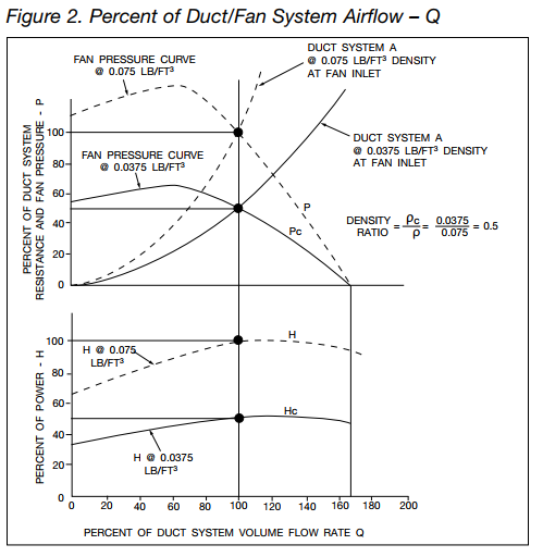
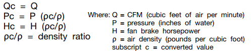
This density ratio must always be considered when selecting a fan from a manufacturer’s catalogs or curves. The dashed curve is representative of cataloged fan performance at 70°F at sea level with a barometric pressure of 29.92" Hg. (standard air). The solid curve is representative of the fan’s performance with an inlet temperature of 600°F at the same altitude and barometric pressure. The fan laws, with the size and speed remaining constant, that apply here are as follows:
So how do we determine the air density for temperature other than 70°F? One way would be to calculate it using absolute temperatures, absolute pressures and barometric pressure, or we could simply refer to Table 1 where it’s been conveniently worked out for a range of temperatures at sea level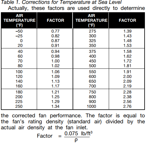
So if the dry air density corresponding to an air temperature other than 70°F is desired, it can be calculated by simply dividing 0.075 by the factor. Fan densities may vary from standard for reasons other than temperature and altitude. Moisture, gas, or a mixture of gases other than air are a few possibilities. For these cases it will be necessary to obtain the actual density of the inlet gas stream by some other reference material. The factor can then be obtained by substituting the new density for ρ. Example 1: A fan is required to deliver 15,000 CFM against 3" SP (static pressure). The fan is to operate at 350°F. This fan would be selected from a manufacturer’s standard rating table or curve for 15,000 CFM at 3" SP at 70°F and would operate at 1,621 RPM and require 12.25 BHP. To determine the fan’s performance at 350°F, simply divide the SP and BHP by the factor from Table 1. The factor for 350°F is 1.53; therefore the operating static pressure and brake horsepower would be as follows:
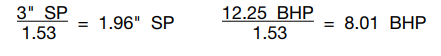
Although the fan RPM is within the speed range specified in the performance tables, the impeller safe speed needs to be verified for operation at the elevated temperature. Most fan manufacturers will list safe speed factors for operation at elevated temperatures in the fan catalog and in their selection software. Caution is required when selecting the motor. From the BHP calculation it appears that either a 71⁄2 or a 10 HP motor could be used. But perhaps the motor selection should be based on a cold start of 12.25 BHP, to allow the fan to start before the air warms up. In this case the fan would require a 15 HP motor. An alternative to a larger motor, depending on the fan’s BHP characteristics, could be a shutoff damper that would not open until the air is up to temperature. For this particular fan, the shutoff power requirement is 6 BHP at standard conditions.
Example 2: Let us look at Example 1 another way. Suppose the request is for a fan to deliver 15,000 CFM against 3" SP at 350°F. In this case the designer is asking for a fan to develop the 3" SP at 350°F inlet temperature. In order to select the fan from the 70°F standard performance tables, we must first convert the static pressure at 350°F to 70°F. We accomplish this by the factor established in Example 1
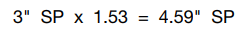
So for this example, if we select the same fan model, our new requirements are for 15,000 CFM at 4.59" SP at 70°F. The fan would operate at 1,742 RPM and require 16.18 BHP. It then follows that the operating conditions at 350°F would be as follows:

CFM and RPM would not change. And again, check the maximum speed limitations of the impeller and proper motor size for the cold starts. Also, keep the following in mind when using temperature correction factors: 1. At temperatures higher than standard air (70°F) the air density is less (lighter air); therefore both the pressure and brake horsepower will be less. 2. At temperatures lower than standard air the air density is greater (heavier air); therefore both the pressure and brake horsepower will be more.
Altitude Effect
Fans operating at some altitude above sea level are similar to fans operating above 70°F. The higher the altitude the less dense (lighter) the air. Altitude correction factors for 70°F air are listed in Table 2. Note that these corrections correspond to average barometric pressure at the stated altitude. Actual conditions will vary with the weather.
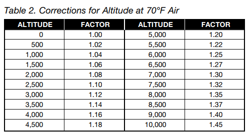
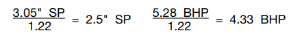
Example 3: Select a fan to deliver 8,500 CFM at 21⁄2" SP at 5,500 ft elevation. Since no temperature is given it will be assumed to be 70°F. From Table 2, the factor for 5,500 ft elevation is 1.22. Converting the static pressure to sea level to use the manufacturer’s performance tables results in: SP = 1.22 x 21⁄2" SP = 3.05" SP at sea level and 70°F. Selecting a fan for 8,500 CFM at 3.05" SP results in an RPM of 1,173 and 5.28 BHP at sea level with 70°F entering air temperature. At the operating conditions of 5,500 ft elevation the SP and BHP would be corrected to:
CFM and RPM would not change. Confirm that the RPM is within published speed limits. The motor horsepower should be okay because the temperature does not vary and the elevation cannot change.
Temperature and Altitude Effect
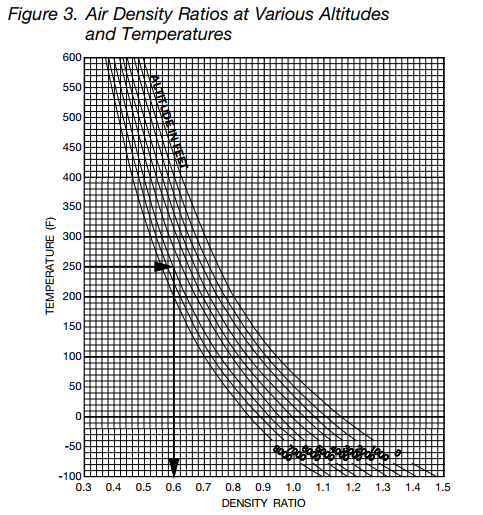
When both temperature and elevation changes are present, the air density must be modified by a factor from both Tables 1 and 2. An alternative to this would be to use a single density ratio number such as can be found in Figure 3
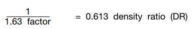
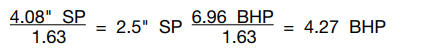
Example 4: Select a fan to deliver 8500 CFM at 21⁄2" SP at 5,500 ft elevation at 250°F. From Table 1 the factor for 250°F is 1.34 and from Table 2 the factor for 5,500 ft elevation is 1.22. The overall factor is obtained by multiplying these factors: 1.34 x 1.22 = 1.63. To use a fan manufacturer’s performance tables, convert the SP to standard air:

The fan will be selected for 8,500 CFM at 4.08" SP and will operate at 1,287 RPM, 6.96 BHP. Converting to operating conditions results in:
And again, CFM and RPM will not change. Also, if the fan is to start cold, it will still be at 5,500 ft elevation. Therefore, to obtain the “cold” horsepower, divide the standard air horsepower by the altitude factor only.
Identical results can also be achieved by using Figure 3. Locate the temperature on the left-hand scale and proceed horizontally to the intersect of the altitude curve, and then follow it vertically down to the density ratio at the bottom of the graph. For a temperature of 250°F and an elevation of 5,500 ft, we read a density ratio of 0.613. The density ratio is simply the reciprocal of the factor.